
|
St. Paul MN 55112 |
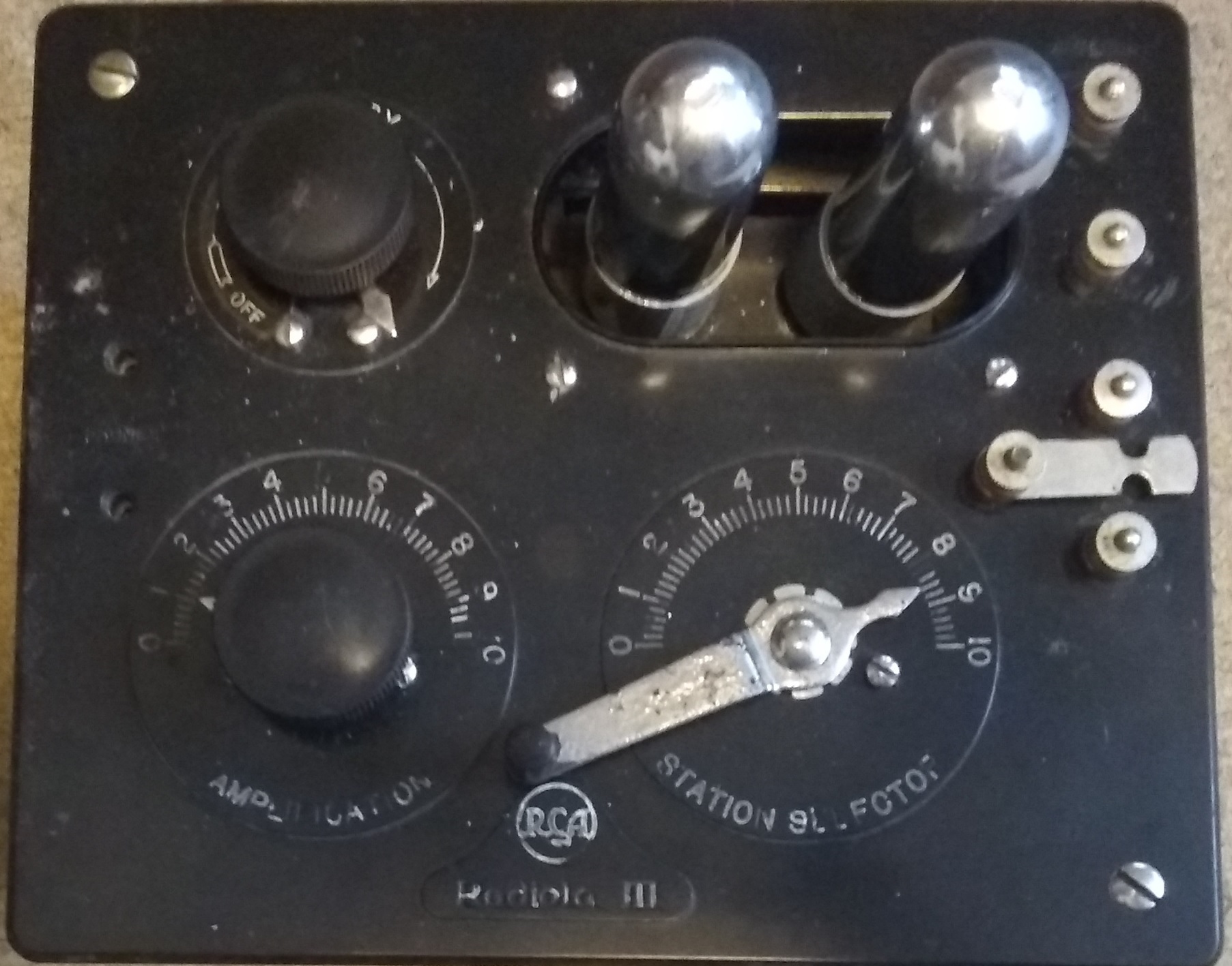
Radiola
III
My Radiola III appears to be older than most The original WD11
tubes are very fragile and expensive. Shown here are
replacements built from a kit. For more information
click this link: Or order kits available here: The WD11 kit
provides performance identical to the original WD11
including full volume control and power off in the full
counter-clockwise position of the "Battery Setting"
control.
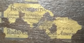
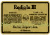
My radio label on left and typical later label on right. Most of the label is gone but it is still possible to see "Regen__ative .." which indicates a unit from the initial production run.
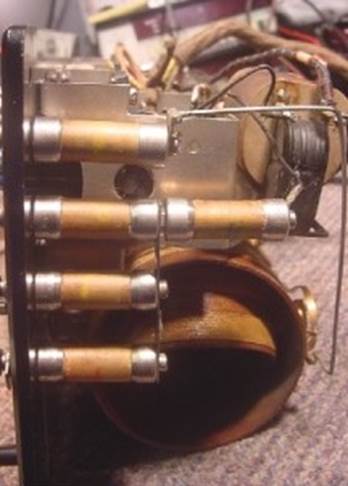
The picture on the left shows a typical Radiola III with four input capacitors and the grid leak resistor-capacitor combination mounted to the right of the second capacitor from the top. Sometimes called Gen 2. The picture on the right shows my Radiola
III, probably older, sometimes called Gen 1.
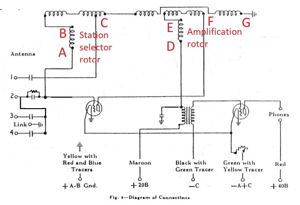
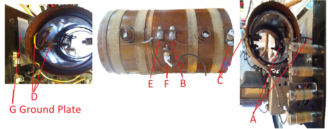
Most schematics on the web show the arrangement in the left picture. A schematic showing the arrangement in the right picture follows. Gen 1 Radiola III Schematic Coil assembly contact points are marked on the next picture and keyed to the points identified on the schematic.
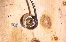
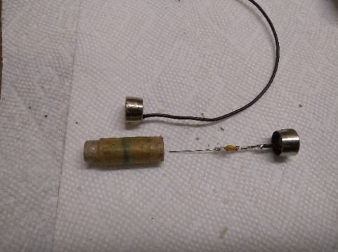
Since the Grid Leak resistor measured open in my radio I removed and disassembled it then replaced the internals with modern parts. These pictures show some of the steps
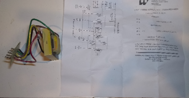
The
interstage transformer between the detector and audio
amplifier had failed. I
replaced it with a new transformer model 118944 by Hammond
Manufacturing. I
bought mine from Digikey, but
it is available from many sources.
The transformer is designed to work in either the Radiola III or Radiola
IIIA so the secondary is center
tapped for the IIIA. The
primary terminals are 1 and 4 and secondary terminals are 2
and 3 for the Radiola III and
terminal 5 is not used in the Radiola
III
The Varactor (large movable coil) had some damage, possibly from rodents. I rebuilt a portion of the coil form and replaced two and a half turns of wire.
|